Construction pits and construction sites
A construction pit is required to be able to build underground. SOCOTEC provides construction site advice for various structures, such as cellars, underpasses, wind turbines, and more
Construction pit advice looks at which facilities are required to be able to carry out the underground work in light of the subsoil, construction and the surroundings. Depending on the situation, the construction pit advice covers various components, such as the retaining wall or slope stability, dewatering, the impact on the surroundings, etc.
In addition, SOCOTEC also provides foundation advice for various types of construction cranes.
Talk to our experts


Our expertise
Retaining walls
Retaining walls are used in situations where it is not possible or undesirable to bridge a difference in height in the ground level with a slope, for example in construction pits or at edges adjacent to water (revetments).
A retaining wall can comprise:
- L-shaped concrete or plastic retaining walls
- Plastic sheet piling
- Wooden retaining walls
- Steel sheet piling
- CSM walls
- Pile walls
- Jet grout walls
- Diaphragm walls
- Injection of foundations with water glass
In the case of great retaining heights or to optimise the design of the retaining structure, the retaining wall can be supported. This support can be achieved by:
- Anchoring using anchor plates
- Anchoring using folding anchors
- Anchoring using grout anchors
- An outrigger frame using steel tubes
- Construction pits
Construction pits
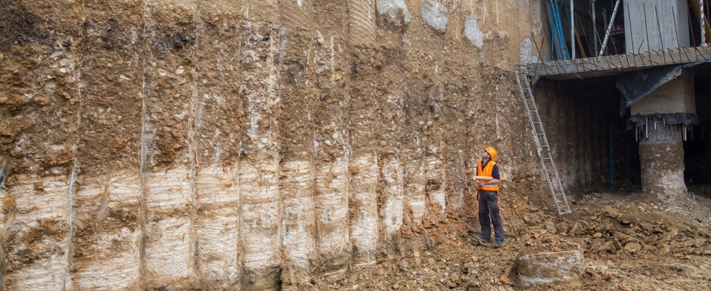
For the installation of underground structures such as foundations, cellars, tunnels, pipes, sewers, etc., a construction pit is required. A construction pit’s function is to handle the necessary excavation with as little impact on the surroundings as possible. The way in which a construction pit can be constructed depends on the type of building, the soil structure, the geohydrology, the applicable regulations and the surroundings.
A construction pit has a vertical and a horizontal boundary. The boundary can be achieved in different ways. The vertical boundary can, for example, consist of a slope, an earth-retaining wall or a water barrier. The horizontal boundary consists of the natural soil structure or an artificial layer (such as water glass injection, grout injection or underwater concrete).
Depending on the situation, the following construction pit variants can usually be used:
- An open construction pit. The construction pit is excavated at a slope or partly with the aid of an earth-retaining wall. Depending on the depth of the excavation, dewatering is necessary to control the groundwater
- A construction pit that is completely enclosed by a retaining wall. If the working space or soil structure does not allow excavation at a slope, you can opt to enclose the construction pit with a retaining wall. The retaining wall can comprise, for example, a sheet pile wall, CSM wall, diaphragm wall, jet grout wall, etc. Depending on the depth of the excavation, dewatering is necessary to control the groundwater
- A closed construction pit. If the working space, soil structure, geohydrology or surroundings do not allow working with a construction pit without a vertical barrier and without horizontal sealing, it may be necessary to work with a closed construction pit. In this case, a ground and water barrier are installed around the construction pit. The bottom seal can consist of naturally water-inhibiting clay, peat or silt layers, or an artificial layer of underwater concrete or water glass/jet grout injection. In the construction pit, the groundwater level can then be controlled with a dewatering system


- Design
SOCOTEC can advise you with regard to the optimum design of a retaining wall and the optimum construction pit method in relation to the type of building, the soil structure, the geohydrology, the applicable regulations and the surroundings. We have many years’ experience with small projects such as the construction of cellars for private homes, as well as making large and deep excavations for receiving and pressure wells for pipes, foundation blocks for wind turbines and multi-storey cellars in inner cities.
We can advise and assist you with an initial Sketch Design (SD) so that the right choices can be made at an early stage, the Preliminary Design (PD), Final Design (FD) and ultimately the design for the construction phase.
For the design we use a geotechnical soil investigation as well as a geotechnical laboratory investigation that we can carry out ourselves. For the design calculations we generally use the D-series by Deltares (D-Sheet Piling and D-Geo Stability). For more complex situations, for example with deep construction pits, Plaxis 2D/3D is used for the design.
- Environmental monitoring
In order to limit the impact on the surroundings as much as possible, environmental monitoring during the work plays an important role in making a construction pit. Monitoring can identify uncertainties during execution so that risk-mitigating measures can be taken at an early stage.


- Soil investigation
To determine the bearing capacity of the underground, the soil investigation that was carried out for the new building is often used. If no survey is available or the crane is more than 15 meters from the available CPTs for the new construction, it is recommended that a survey be carried out with at least two CPTs (NEN-EN-ISO 22476-1) and manual drilling (NEN -EN ISO 14688-1). In specific cases, such as for a heavy crawler crane in areas with weak soil layers, a more extensive survey is carried out with laboratory research to get a good picture of the properties of the underground.
- Foundation on steel
With a foundation on steel, the stability is tested analytically, whereby the gear tooth contact pattern of the crane is regarded as a foundation on steel in accordance with NEN 9997-1. This involves testing for both the geotechnical bearing capacity (drained and undrained) and for punching through on the basis of the expected loads on the crane, the dimensions of the outriggers/tracks and the underground. In projects with high and heavy lifting, horizontal loads due to wind forces on the crane as well as the turning and swinging of the boom are taken into account. The bearing capacity strongly depends on the combination of the size of the load-bearing surface, the loads on the crane and the underground, and is not a fixed value. It is therefore important that the specific details of the crane are provided when formulating a recommendation. The deformations are also considered in relation to the dynamics and duration of the hoisting work. We can check the stiffness of the installed foundation packages for you with plate load tests and cone penetration testing.
- Pile foundation
With a pile foundation, the calculation of the pile bearing capacity and the deformations is based on NEN 9997-1. The effect of horizontal loads on the pile heads is also modelled to determine the required reinforcement in the piles. It is recommended to measure the foundation piles acoustically, to be sure about the integrity of the pile shaft.
Finally, it should be noted that the position of the crane in relation to adjacent structures also influences the type of foundation. In the case of a crane with a steel base right next to an (existing) cellar, horizontal loads on this cellar must be taken into account. The same applies to sensitive piping/cabling in the underground under or close to the crane. We can also offer advice with regard to these aspects.
Dewatering and its impact on the surroundings
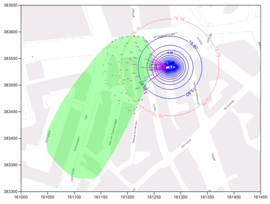
If groundwater needs to be extracted, SOCOTEC can provide dewatering advice. Using field and laboratory tests and archival research we create a schematic representation of the geohydrological subgrade and the groundwater regime at a location. We then use a model calculation (Modflow or MicroFEM) to calculate the expected extraction flow during the execution of the project, for example a construction pit, the total amount of water extracted during the dewatering period and the size of the area affected by the dewatering.
SOCOTEC tests the extraction flow rates and the amount of water extracted against the competent authority’s rules that are relevant at the site to investigate whether your dewatering is subject to a permit requirement. If a permit is required, we can take care of applying to the competent authority for the water permit for you.
We then conduct a study into the impact of the groundwater extraction on the surroundings. Additional analyses might be necessary, for example a shift in the fresh/salt water interface or the displacement of contaminants. SOCOTEC can also do these calculations for you.
Deformation of or in the underground can occur as a result of (geohydrological) activities, for example by lowering the groundwater level for dewatering. This aspect has a certain impact on the surroundings, such as on the infrastructure above and under the ground, archaeological finds in the ground, (foundations of) buildings or water barriers. Depending on the degree of impact, damage may occur to the aforementioned objects. What’s more, a (temporary) drawdown of the groundwater level can also have an impact on nature and agriculture, can cause any contaminants present to spread or displace in the subgrade and any fresh/salt water interfaces to shift.
SOCOTEC can advise you with regard to this impact on the surroundings. This could include:
- Preparing settlement analyses for lowering groundwater levels and the impact of lowering groundwater levels on buildings and infrastructure
- Flow path analysis
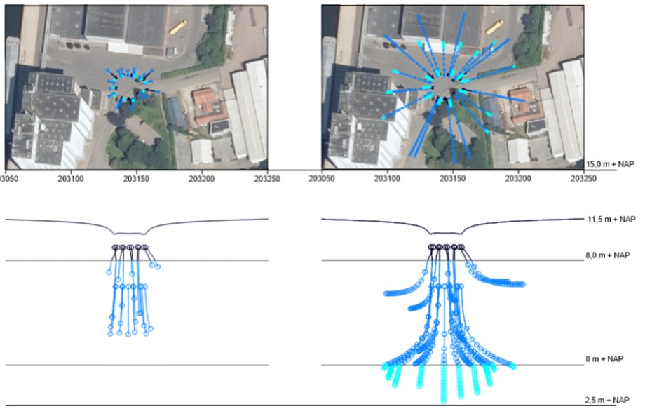
For these analyses we use geotechnical soil investigations as well as geotechnical laboratory tests that we can carry out ourselves. For the calculations we use our own software, the D series by Deltares (D-Settlement) and (Modflow or MicroFEM).
A water permit is only granted if the negative impact on the surroundings is sufficiently small. In the event of a negative impact on the surroundings (for example, the displacement of contamination), SOCOTEC will determine together with you and the competent authority what the best solution is to mitigate the impact. We do not round off the reporting until it is clear that the impact on the surroundings will be sufficiently limited. Only then do we apply for the water permit to the competent authority.
Slope stability
By elevating (or placing a load on) the ground, or excavating (for example a construction pit), the balance of forces in the underground changes at the transition between the elevation (load)/excavation and the original ground level. This creates (additional) shear stresses in the underground. If the maximum shear stresses that can be absorbed by the underground are exceeded, the underground will collapse and become unstable.
Stability analyses can be useful for every phase of your project:
- In the design phase (final design) to determine the geometry (which slope, dimensions of any stability berm, etc.) so that a design can be obtained that meets the specified standards for final stability
- In preparation for the realisation phase (design for the construction phase), to determine the rate of elevation at which the embankment can be constructed in phases without instability occurring in the underground and possibly causing damage to the surroundings
- During the realisation phase itself (see Site Engineering)
With regard to the aforementioned provisions, depending on the phase of the project and on the circumstances, consider the following:
- Reducing the angle of the slope (final design, design for the construction phase, realisation phase)
- (Temporary) installation of a stability berm (final design, design for the construction phase, realisation phase)
- Install vertical drains (design for the construction phase, realisation phase)
- Soil reinforcement work, for example in the form of a geotextile (final design, design for the construction phase, possibly in the realisation phase)
- Allowing more time between elevating successive layers (design for the construction phase, realisation phase)
- Application of light fill material (final design, design for the construction phase, realisation phase)
In addition to the aforementioned traditional arrangements/techniques, there are also innovative techniques such as soil nailing.


In practice, differences may arise between the behaviour of the underground predicted in the design phase and the actual behaviour of the underground during the realisation phase. These can lead to unforeseen deformations and in extreme situations even to instability of the underground (see Site Engineering). These uncertainties can be managed using the so-called observation method. Based on measured actual on-site pore pressures (see pore pressure meters), it is determined how much backfill material may be added to the embankment. If deviations are found between the actual and predicted behaviour of the ground, action can be taken. If there are negative deviations, it is often sufficient to adapt the rate of elevation. The motto here is “faster if possible, slower if necessary”.
The calculations for the stability analyses are generally made with the validated Deltares D-series D-Geo Stability software.
SOCOTEC can perform the stability analyses for you using the most commonly used Bishop, Uplift-Van (uplift model) and (Uplift) Spencer models.
For more advanced analyses, the validated Plaxis software can be used.

